

 The South African
Published in RADIO BYGONES NO 142, April/May 2013
One really has to wonder, now that the word 'wireless' has almost exploded into our 21st century world, whether those responsible for ditching this 'old fashioned term' aren't kicking themselves for having thrown away what may well be the word of the century!
However, to go back a bit to the year immediately after the end of the First World War, electronics hadn't even been invented and the wonder of communicating through space without wires wasn't even called radio, at least not in England. Wireless it was and it was seen as the invention that stunned mankind. But it was more than a novelty; in 1912 wireless undoubtedly saved many lives following the Titanic disaster, and in the war supposedly to end all wars that soon followed, it was put to great use again. Surprising as it may seem, wireless even found its way into the trenches, those places of unimaginable horror for tens of thousands of young men just waiting for the order to go "over the top" and thence to a fate where one's lifespan was often measured only in minutes.
The wireless communications apparatus of the time was of the most elementary kind, but it worked, and its use, especially for artillery spotting, proved to be invaluable. Possibly the first technical description of that equipment, and how it was used in battle, was written by a young officer in the Royal Engineer Signal Service and it appeared in four parts in The Wireless World between July and November 1919 under the title W/T. R.E., army shorthand for Wireless Telegraphy, Royal Engineers [1].
Army Signalling
During the Great War, as it was called for many years afterwards, all army signalling was the province of the royal Engineer Signal Service. This special body within the Corps of Royal Engineers came into being in 1908 as a rsult of the amalgamation of various telegraph batallions, formed to provide communications for the army both by wire and visual means, such as flags and heliograph, from about 1870. With the advent of Marconi's wireless apparatus and its adoption by the British Army as early as 1899 during the Boer War (See RB140), it was clearly necessary to establish a specialised section whose task was to set up and operate this new technological marvel. And thus the word 'Telegraph' was replaced by 'Signal' in the Army in 1910 and so it has been ever since [2].
By 1913, wireless telegraphy was accepted as an integral part of the British Expeditionary Force and training in its use had formed part of the manoeuvres held during that year. Wireless was naturally seen to be the only effective means of communication between the cavalry and GHQ since the existing methods of signalling, which relied predominantly on cables. were obviously useless in mobile situations.
At the outbreak of war in 1914 this was the official situation. However some enterprising officers had already begun to examine other possible uses for this new technology. Amongst these were the problems of communicating with aircraft as well as its use in intelligence-gathering by monitoring the enemy's wireless traffic and feeding the information so gained to the Army's Intelligence Department. But, despite all this, wireless telegraphy was treated officially as "possibly a useful adjunct to visual andline signalling" [3]. We shall now see how useful it turned out to be.
Mobile Warfare
The opening phase of the war was highly mobile. In August 1914. when Britain declared war on Germany, the cavalry was the dominant force in the army and much of their wireless signalling depended on so-calle pack sets used at Brigade level, while l.5kW wagon-borne sets were used at the higher Divisional and General HQs, Figure 1. Since only about a dozen of those mobile sets arrived in France with the British Expeditionary Force in August 1914 [1], communications between fixed installations relied heavily on lines; some used the existing French civil network, while in other areas dedicated lines were laid by the Royal Engineer's cable detachments. These consisted of cable wagons (known as 'hearses') pulled by six horses with three riders, plus another five men riding alongside. The art of cable-laying on horseback was a highly developed skill that was drummed into all its recruits at the RE remount depot at Haynes Park in Bedfordshire.
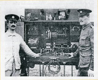
Fig. 1. A wireless wagon and some of its R.E. Signal Service personnel
Communications were now even more vital than before and signalling equipment underwent some significant changes. It was there in the trenches that signalling in general, and wireless in particular, took on a very different role.
Signals And Intelligence
From the earliest days in the development of telegraphic systems, based on either overhead or buried cables, it was realised that only one conductor was required if an effective 'earth return' path was available. This clearly made the installation of such systems both cheaper and easier and so it wasn't surprising that both telephone and telegraph circuits made great use of this method.
Given the sheer volume of 'traffic' that passed along those lines, and returned through that terrestrial circuit, the earth itself was, as noted at the time, "alive with buzzer and telephone induction". This had a natural consequence from the point of view of military intelligence for it meant that all such signals could be intercepted by the simple expedient of attaching a listening device, such as a telephone, to the earth. This was done by means of two widely separated connections achieved by driving two metal stakes into the ground as close to the enemy trenches as both topography and courage would allow.
Initially, the Germans proved to be more adept than their opponents at this earliest form of what we today would call electronic warfare but, once the danger to security had been appreciated and understood, British training and technology took full account of it and used it to good effect themselves. It was around about this time that the so-called power buzzer was developed and was used extensively to communicate via these telluric currents, see Figure 2.
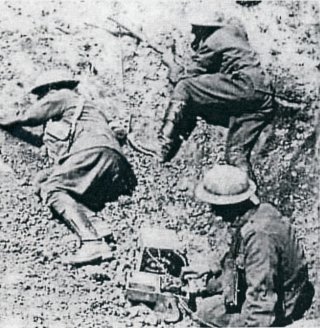
Fig 2. The power buzzer being operated on the front line
This is not the place to describe the Fullerphone in any detail, except to say that Fuller understood the electromagnetics involved in signalling through the earth, and he realised that by sending what were essentially direct current (DC) signals down the line instead of the more usual alternating or AC variety (as generated by the buzzers then in use), the magnetic fields produced would be reduced significantly and this would make 'overhearing', as it was called, a much more taxing process for the enemy.
At the receiving end the Fullerphone converted the DC back to AC again and that produced a tone in the operator's earphones. In between sender and receiver the: signals were ulmost undetectable. However, the Germans continued to use AC signalling on their lines and this provided much intelligence to the British Army, especially when sensitive amplifiers using thermionic valves became available.
Thermionic Valves
Since those earth-return currents were often exceedingly weak, unless the intercepting stakes were very close to the sending circuit, the range over which interception was possible was limited. It was the French who led the way in solving this problem wben they developed a two-valve amplifier, the 'IT' set as it was known, that greatly extended the range to some 2,000 to 5,000 yards and its immediate use by the nritish Army brought about significant improvements in intelligence gathering [3]. lt was this application of the American Lee De Forest's invention of the triode valve that caused British firms manufacturing incandescent lamps to move rapidly into the world of the thermionic valve. And that, of course, was the start of the electronics age.
But we are getting ahead of ourselves. By 1915, communications technology without wires was already well established using spark transmitters and coherer-based receivers. However, the transmitting and receiving apparatus was anything but portable. Not long after the outbreak of War the design engineers back in England faced a completely new challenge: to make wireless equipment small and light enough to be carried by a man, or at least just a few of them. The reason for this was that the war had become almost static.
The rate of advance had slowed from that of the horse and the motor vehicle to that of men almost on all-fours. And the fighting took on a new ferocity between foes, often only yards apart but separated by what was often a quagmire. Massive artillery bombardments became a daily occurrence and, becauseof the very close proximity between friend and foe, accurate targeting was obsolutely vital. Good communiactions between the OP (Observation Post), always situated well forward, and the guns much further back, was therefore imperative.
Wireless in The Trenches
Once the opposing armies were 'dug-in' within their trenches that changed so littl eover the succeeding four years, the large and cumbersome wagon-borne sets were soon withdrawn from service. In addition, the damage done to any cables, buried or not, by the almost incessant artillery bombardments meant that wireless became the only viable means of communication, both foprward to the front line and rearwards to Brigade and Divisional HQs.
The well-established method in previous wars of visual signalling by flag, heliograph and lamp could be used, of course, but the drastically shortened lifespan of those wielding those devices, as soon as they put their heads above the parapet, rather decreased their appeal as a mustering amongst signallers. Needless to say as well, the challenge of being a message-bearing runner on foot, always used only as a last resort, was even less attractive. And so, by the end of 1915, the army had introduced its first wireless sets into the trenches and Tommy Atkins, down there, became used to sharing his abode with 'Sparks' - see Figure 3
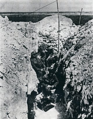
Fig.3. The BF Set, its aerial supports and 'Sparks' in a trench somewhere on the Western Front
The following month he presented himself at the War Office for an interview where be was accepted for a commission in the Royal Engineers, that highly regarded corps within the Army with responsibilities for all manner of things technical, including the new-fangled wireless. ln August 1915 Schonland (Figure 4) began his training at the RE Signal Depot near Bletchley, the town that would acquire an almost mythical reputation during, or at least after, the next world war.
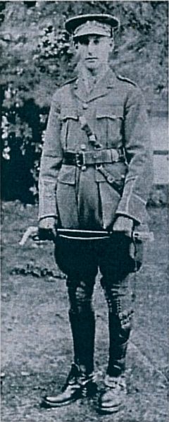
Fig.4. Nineteen year-old second lieutenant Basil Schonland RE in 1915
Among the first wireless sets to be used in the trenches by the British Army was one known officially as the Trench Set, Spark, 50W, but they were much better known by those who used them as the BF set (Figure 5). Whether this was a derogatory term (given the common use of those initials for something quite different in those days) is not certain, but the fact that the equipment was designed to be very simple to use suggests some truth in that. However, when a visiting general or other dignitary put in an occasional appearance at some Signal establishment or another, the operators would demonstrate the workings of the 'British Field' set, thereby preserving decorum.
The BF set, with its various cables and the poles to support its aerial, was light enough to be carried by three men. However, carrying the 20Ah accumulators required to providee power to sustain its operation for the often lengthy military engagements was another matter. Many more men were 'volunteered' for that task. The BF set spark transmitter and the biased carborundum crystal detector (but without any amplification) in the receiver operated at wavelengths of 350, 450 and 550 metres or from about 545kHz to 860kHz. These were the agreed wavelengths following careful coordination with the Royal Flying Corps (RFC) who were, by that stage of the war, making considerable use of wireless communications between their aircraft and ground control stations.
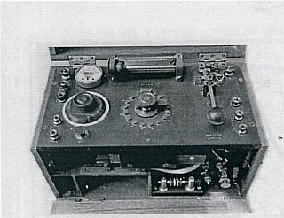
Fig.5. The BF set or Trench Set, Spark with its spark gap clearly visible
Wires, Tees And Ground Aerials
It is worth considering these various antenna configurations for a moment because it is, after all, the effectiveness of the antenna that determines whether a radio communications link works or not.
One would indeed expect this rather short T aerial to perform better than the much longer end-fed version for two reasons. First, the vertically polarised signal it produced would propagate far better in the ground-wave mode than the horizontal component radiated by a horizontal wire. The other factor is that a T aerial has the benefit of considerable capacitive loading from its horizontal top-section. This helps to maintain an almost constant current distribution along the vertical wire; thereby improving its radiation efficiency compared with a simple vertical element without top-loading.
But often such 'ideal' aerials could not be put up and then all that the wireless operator ('Sparks', of course) could do was to throw out as long a length of insulated wire as he could manage. In actual fact the practice was to throw out two lengths of wire; in opposite directions, with the BF set between them. This 'ground aerial', a dipole or doublet as we would recognise it today, did radiate to some extent but it was severely compromised and worked worst or all when the ground around the aerial wire was wet, as it frequently was in winter. However, according to Schonland, some very important messages were passed using these inadequate aerials and frequently, enemy counter-attacks were repulsed as a result.
As an illustration of where the BF sets were deployed during those terrible days in 1916, there is a useful map in Schonland's article (Figure 6). What is so evident was the tortuously slow rate of advance possible during the First Battle of the Somme. Mobile warfare it most certainly wasn't. In three months, the front line moved no more than twenty kilometres. However, it is also clear that the various BF sets, with their frequently inadequate aerials, were capable of working over those sorts of distances from places whose names are now very much part of WWI history and its folklore. Wireless was certainly making its mark on the battlefield.
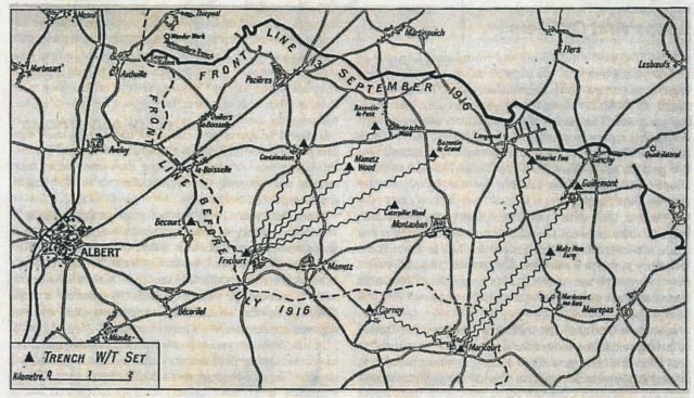
Fig.6. A map showing the use of wireless during the first battle of the Somme, September 1916
Loops And CW Sets
In 1917 a new wireless set was introduced. Claimed to be 'extremely portable' [3) (though this is surely a relative term) it was, to give it its formal title, the W/T Set Forward Spark 20 Watt B. However. it soon became known as the Loop Set. The reason was its peculiar aerial, a small collapsible square loop of brass tubing just a metre per side that could be clamped to a bayonet and then rammed into the ground, see Figure 7. Its operation was particularly simple, making it most suitable for use by technically unskilled operators.
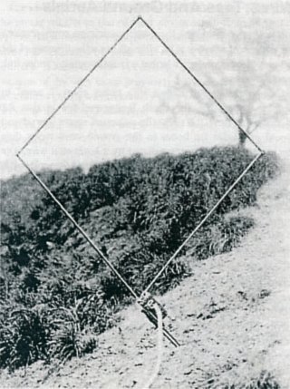
Fig.7. The Loop set aerial on a bayonet stuck in the ground
Of course, their ability to send and receive the Morse code was still a sine qua non. The other feature of the Loop Set that made it unlike every other wireless set then in use was the frequency at which it operated. This was the true short-wave set. It worked on one of two fixed wavelengths of 65 and 80 metres and was claimed to be effective over a range of 2,000 yards [4].
Also novel was the method of tuning the transmitter. lnstead of having within the transmitter a selectable resonant circuit that determined the operating frequency, as is normal practice, it used the loop aerial itself to provide the inductance with both the resonating capacitor (or condenser in those days), and the transmitter's spark gap, housed together within a small ebonite box on which the loop was mounted. It is interesting to note that this is probably the earliest use of what we would now call an electrically small loop antenna, sometimes (though misleadingly) called a 'magnetic loop' .
The rest of the transmitter, usually below ground level within a trench, consisted of a high-tension supply and a Morse key connected to the loop by 20 feet of cable. In a separate case was the receiver. This too was very advanced for its time for it included two triode valves, the new French type known as the Telegraphie Militaire or TM valve, perhaps better known as the R valve when in civilian use. Its role was as audio amplifiers following the detector.
It should be appreciated that spark transmitters made their own peculiar sound, rich in audio tones which could be heard over earphones. A most interesting demonstration of these sounds, made recently by Dr Jack Belrose VE2CV, can be found on the internet link [5].
That same year, 1917, saw an even greater advance, in wireless telegraphy when a continuous wave (CW) transmitter was developed at Woolwhich, based on a design by Major Rupert Stanley of the Royal Engineers. Not surprisingly it became known as the CW set when it went into service midway through the year (Figure 8). It contained a single TM valve used as an oscillator when transmitting and as a regenerative detector when receiving.
In later versions, two valves were used in the receiver: one as the oscillating detector, the other as an audio amplifier. At a DC input power of about 30 Watts the set covered a frequency range from around 220kHz to 600kHz and it used the usual, long wire aerial and earth mat arrangement described above.
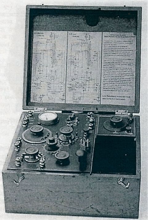
Fig.8. The W/T Trench Set CW Mk 1, 30 Watt
Performance In Battle
According to Schonland, the CW set proved to be very effective in battle even when circumstances demanded that the aerials be as low and as short as possible. The CW set was, he said, of "incalculable value to artillery and other units" and he went on to describe with much verve and enthusiasm how those sets found particular favour with the 'gunners' [1].
"If difficulty was experieced in laying and maintaining telegraph lines for infantry 'command' purposes, the difficulty here was still more acute. The cry from the artillery was for more CW sets, and still more! With the Forward Observation Officer in his OP, with the guns themselves or with the headquarters of the artillery brigade, the valves of the CW sets were flickering night and day, and that their success was great is beyond any doubt."
Similarly, he told how the Canadian Independent Force used the CW set to great effect when engaged in highly mobile operations. Evidently, this "'most formidable collection of armoured cars, machine guns and pompoms mounted on cars and lorries" set forth or, as he put it much more expressively, "sailed into the blue" to engage machine gun nests, and anti-tank guns with great success. One car carried a CW set, though he omitted to mention what antenna it camed, with which it maintained contact with its headquarters behind the line, thereby keeping it informed "of the progress of events elsewhere".
Similarly, parties of scouts working as special-observers all along the front line sent back their reports by wireless and they were always using the CW set. It is interesting to note that this activity was very similar to that of the unit known as 'Phantom' in the next war. The distances over which they communicated "without the slightest trouble", according to Schonland, were from ten to twenty miles. No mean feat, one has to admit, given the fact that the aerials, whatever their size and configuration, would, per force, have been very small when measured in terms of wavelengths; the criterion of performance.
Control And Coordination
Naturally, when wireless began to play an increasingly important part in military operations (and never forgetting that the enemy was so equipped as well), the need for careful planning, control and coordination was paramount. The proximity of various military formations one to another, and the number of different wireless 'nets' which served each, is shown in another map from W/T. R.E. (Figure 9). These nets were arranged in what was then called the Group System serving Army, Corps, Division and Brigade, as well as all the formations below them.
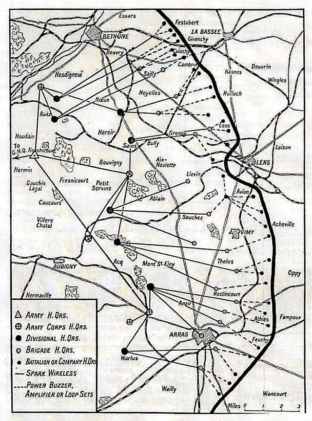
Fig.9. A map showing the disposition of the British First Army
and its wireless communications prior to the great offensive in August 1918
Different types of wireless sets were used at various levels of command and in different areas. To illustrate how this was all done, Schonland included a table, as well as a diagram showing specifically how wireless nets were established for control of the artillery and the communication with the RAF whose aircraft provided target-spotting for the guns on the ground (Figure 10).
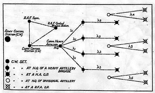
Fig.10. A diagram showing the communications within the artillery
and also within the RAF target-spotting aircraft
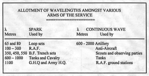
The biggest problem with all complex military wireless networks like this is tbe possibility of interference between the various users. It was therefore necessary not only to allocate operating frequencies judiciously but also to monitor the activity and take the appropriate corrective action if necessary. This was the job of control stations that searched from wavelength to wavelength and listened in for long enough to detect both interference and poor operating procedures. Once more, as Schonland relates, the Canadians distinguished themselves by making a CW receiver "capable of simultaneous reception on seven wavelengths" to aid in this monitoring process. This engineering feat will have enhanced their monitoring capabilities no end!
Monitoring And Deceiving The Enemy
Wireless techniques soon found their way into the intelligence-gathering world. Both sides monitored each other's transmissions and so messages were, of necessity, encoded. This immediately saw the establishment of what were called 'Wireless Observation Groups' whose activities involved both wireless direction finding or, as it was called at that time, position-finding (PF), as well as the decoding of enemy messages. This latter activity, according to Schonland, involved the recruiting of acrostic-solvers from amongst the ranks of readers of the daily papers whose acrostics, or crossword puzzles, provided "a good preparation for wrestling with German messages". Such skills, and similar training, were to prove rather important during the next encounter too!
Wireless direction finding made great strides during those frightful days on the Western Front. Again it was the part played by the thermionic valve that was significant, as were the improvements made to the well-known Bellini-Tassi crossed-loop DF aerial system. By using high gain valve amplifiers it proved possible to decrease the size of the DF antennas and even to dispense with the rather bulky (and heavy) goniometer system in which one multi-turn coil was rotated within another as the means of finding a null in the received signal.
The greater sensitivity provided by the valves meant that the Bellini-Tassi IOQPs themselves could be made much smaller and therefore were easily rotated to achieve the same purpose.
From W/T. R.E. To 21 Army Group
In mid-1918 Basil Schonland was promoted to the rank of captain and was placed in charge of all wireless communications in the British First Army preparing for the advance from Arras to Mons. At the age of just 22 he had reporting to him 30 officers and more than 900 men, and was responsible for over 300 wireless sets. Before this, at the end of 1916, he had left the front line and was posted to the Central Wireless School at Montreuil where he Served as Wireless Research Officer attached to the Wireless Experimental Section BEF and also as the instructor-in-charge of officers' courses of instruction. There, during 1917, he and a fellow officer by the name of Spencer Humby carried out some research on using a triode valve as an oscillator [6].
In a letter home, written in July 1918, Schonland told his younger brother that "GHQ are making a wonderful new wireless set as a result of that research that Humby and myself undertook". Naturally, the results of their research were kept secret during the war but they were published in 1919 following similar work back in England, published the year before, by another RE Signal Service officer by the name of Edward Appleton. Appleton, of course, was soon to make his mark in an.entirely different aspect of radio communications as the discoverer of the ionosphere [7]. Together, those two papers proved to be of much significance in the early days of CW wireless systems.
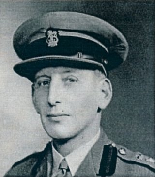
Fig.11 Colonel Basil Schonland soon to become scientific adviser to Montgomery in 1944
Schonland was not a professional soldier. After the war be returned to Cambridge to continue his research under the direction of Lord Rutherford but not before the Army had tried very hard to keep him. He was offered the position of Chief Instructor in Wireless in the British Army and with it the rank of major. But he was intent on pursuing a scientific career and he declined. However, he was not lost to the colours. In 1939, at the outbreak of war, and now back in his native South Africa, where he was a world-renowned expert on lightning, he took on the task of developing a radar system for the defence of South Africa's very long coastline. That work soon brought him to England where be became Superintendent (in the rank of colonel) of the Army Operational Research Group (AORG), and in 1944 be was appointed scientific adviser to the Commander-in-chief, 21 Army Group, General Sir Bernard Montgomery. This was just prior to the D-Day Landings and the invasion of north-west Europe by the allied forces under the overall command of General Eisenhower.
Brigadier Schonland (Figure 11) served with distinction in that role and was awarded the CBE (mil.) to follow the OBE (mil.) he'd received after the First World War. Once the war was over he again returned to civilian life in South Africa to be appointed the founding President of the Council for Scientific and Industrial Research (CSIR) and then, on returning to England in 1954, he ultimately became the Director of the Atomic Energy Research Establishment at Harwell from where he retired, with a knighthood, in 1960 [8].
Acknowledgements
Acknowledgements to Louis Meulstee for the use of the photographs of the BF set and the Loop Set aerial and also to Tim Stankus, Royal Signals Museum, Blandford for his considerable assistance over the years with information, numerous illustrations and documents. Sincere thanks too to Dr Mary Davidson, Schonland's daughter, for permission to use the photographs of her father.
References
Return to Journal Index OR Society's Home page
South African Military History Society / scribe@samilitaryhistory.org